HEADLAMP SWITCHING MODIFICATION MARK 2
DO NOT BUILD UNTIL THIS NOTICE IS TAKEN DOWN
IT'S A DESIGN IN PROGRESS AND IS INCOMPLETE BEFORE THEN
This design improves vehicle headlamp brightness by
reducing the voltage drop associated with the length and gauge of
wiring normally fitted to the headlamp circuits.
It is designed specifically for the Citroën BX and for the
use of BXClub members - see
BXClub.co.uk and has
the same functionallity as the original design.
OVERVIEW
The Citroën BX has basic switching for sidelights, dip and main beams. When
both sidelights and ignition are on the dip filaments are driven at low
intensity - "dim-dip" - this prevents the car being driven on sidelights
alone.
The electronics in this design is only responsible for the dim-dip function
and only differs from the original in that the brightness of dim-dip is
adjustable and almost entirely avoids the slight inefficiency
of the original resistive design.
Dip beam and main beam functions are operated by relays with power being
derived from a new high current (and therefore low voltage drop) wire direct
from the battery.
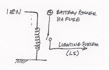
POWER SOURCE
In order to reduce voltage drop to the headlamps a high current wire should
be fed from the battery to the headlamp area to feed the new control
arrangement - this should be fused at the battery end to reduce the risk
of fire in the event of serious front end damage to the vehicle which could
short out the wire to chassis. A 20 amp fuse should suffice unless high
power filament are used and additional lighting such as spotlamps are
driven from the same wire.
One way to provide power to the electronics is by using a relay.
MAIN CIRCUIT
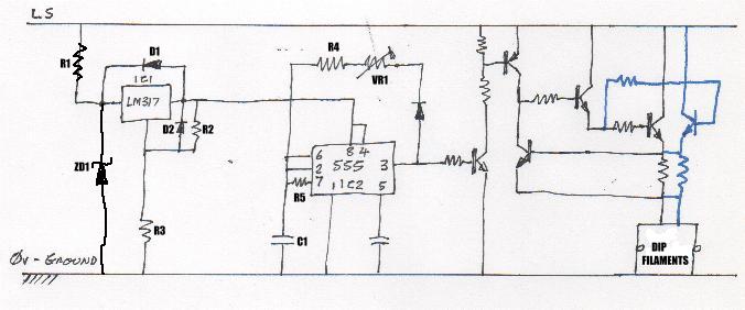
CIRCUIT DESCRIPTION
IC1 provides stable regulated power for IC2. A further description of
the LM317T including this particular circuit configuration is at
IC2 is an oscillator with an adjustable mark / space ratio which drives
pulses into the next stage. A more detailed description of the 555 timer
including this particular circuit configuration is at
The remaining circuit consists of a power buffer with current limiting
and is adequately described on the LM317T page link as above.
The circuit drives power in the form of pulses to the dip filaments.
The frequency of these pulses is too high for the filaments to respond so
they glow in response to the average amount of power delivered to them.
When the circuit is started the filaments are very low resistance and the
current limiter will operate to protect the drive transistors but when
the filaments have warmed to their operating temperature their resistance
will be high enough for the limiter not to operate. At this point the output
transistors will either be "on" or "off" and so will waste very little power
and should run dissipate very little heat.