VEHICLE ELECTRONICS POWER
When fitted to a vehicle, electronics circuits need a reasonably stable DC
power supply so that variations in voltage including high voltage spikes
and dropouts do not interfere with the circuit operation. Described here is
a circuit based on the LM317T regulator IC which fulfills - and indeed exceeds
all the requirements.
The LM317T is a 3 pin device which produces a very well regulated output
approximately within the range of 1.25 to 38 volts depending on input voltage
and associated circuit design.
Full datasheet is here
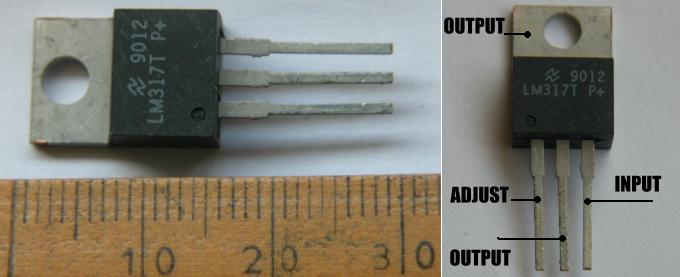
The 3 pins are designated "input", "output", and "adjust" and the device
operates by setting the output to 1.25 volts above the adjust pin.
It requires
5mA current flow through the resistor control network to operate correctly
so Rb is (R= V/I ... R=1.25 / 5mA = 240 ohms) - a higher value could cause
problems with stability - a lower value would waste current so 240 ohms is
almost invariably used. A lower value can be used when regulating current rather
than voltage.
Note that the output - the middle pin - is connected to the tab - so if you
attach this device to metalwork with a nut and bolt then the metalwork is
connected to the output. Since most metalwork on a vehicle is connected to
"ground" - the negative terminal of the battery - otherwise referred to as
"0 volts" or "0v" this will short out the output of the LM317T. Insulating
kits are available which include a mica washer to go between the device and the
metalwork or heatsink and a "top hat" plastic insulator for the screw. For
low currents it's normal not to use the mounting hole and just solder the
connections to a PCB or "breadboard".
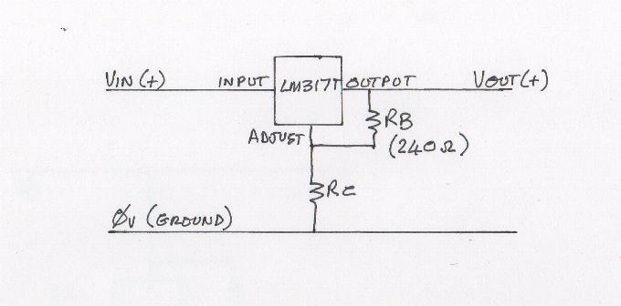
5mA flows through Rb and Rc so the output voltage is set by choosing - or
adjusting Rc to a particular value. For example - if we chose Rc to be 1000 ohms
then the voltage across it will be (V= I x R = 5mA x 1000 = 5 volts) added to
the voltage across Rb which is always 1.25 volts we have a regulated output of
6.25 volts.
If we short the adjust pin to ground - ie: make Rc zero ohms, then the output
pin will be at 1.25 volts.
The LM317T needs the input to be around 4 volts higher than the output voltage
so in the above example the input would need to be at least 10.25 volts.
The LM317T is rated at 1.5 amps - but it will only regulate this much current
if it is attached to a large heatsink. Lower currents can be achieved without
a heatsink.
The LM317T is internally protected against over-current and over-temperature -
it shuts down completely at 150?C. It is NOT protected against reverse
voltages - adjust and / or output pins at a higher voltage than the input -
and it is NOT protected against voltages on the input (with respect to any
other pin) greater than 42 volts. The following circuit additions protect
against both of these and make the circuit design "bulletproof".
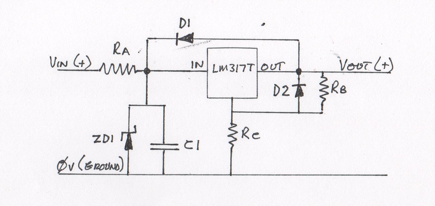
The value of Ra should be low enough to allow enough current to operate the
circuit connected to the supply output and ZD1 and C1 should be chosen to
protect the regulator and supply backup power in case of dropouts respectively.
This is more complex than I intend to deal with here and depends very much on
the conditions being designed for.
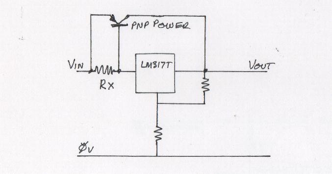
Components may be added to the design to increase the current available from
the output as in the application notes for the LM317T. Additional current is
supplied by the power transistor (power buffer) but the output voltage
is still fully controlled by the LM317T. When the current increases to the
point where the voltage drop across Rx exceeds about 0.6 volts, the
power transistor begins to conduct and supply additional power to the
output independently of the LM317T.
Other designs may be produced for specific purposes - I produced the design
below as part of a regulated power supply featuring a version of the power
buffer which is integrated with a current limiter. This became known as "The
Dog's Bollocks" current limiter because of its precise and stable operation. The
power transistors must be fitted to a heatsink.
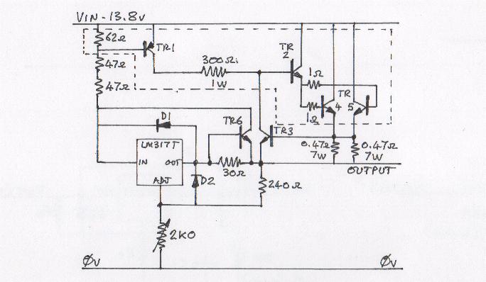
TR1 is a BD242A
TR2, TR3 and TR6 are BD241A
TR4 and TR5 are 2N3442 on heatsinks
The circuit within the dotted line is the power buffer.
It is a regulated power supply with 13.8 volts input and 1.25 to about 10
volts output. The LM317T supplies current to the output up to only 15mA
any further load being dealt with by the power buffer. At 2.5 amps output
the current buffer is progressively shut down by the action of TR3 and the
output current remains at 2.5 amps even when the output terminals are
shorted together.
Note the operation of the power buffer...
When the current feeding the LM317T reaches about 9.7 mA the voltage across TR1
base / emitter reaches about 0.6 volts and this starts to turn the TR1
on, feeding a small amount of current through the 300 ohm resistor. This
current is amplified through TR2 and fed through two 1 ohm resistors to the
bases of the output transistors TR4 and TR5. The outputs of these two
transistors are fed through a pair of 0.47 ohm resistors to the output of
the supply. When the current through each of these resistors reaches about 1.25 amps
there is 0.6 volts across them which starts to turn on TR3 which reduces,
or "clamps" the small current feed through the 300 ohm resistor.
Since it is this small current which drives the current buffer the output
is stabilised at 2.5 amps.
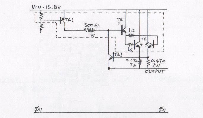
The output buffer plus current limiter can be used on its own - a signal
(AC or DC) applied to the base of TR1 sufficient to drive the output will
only produce an output of up to 2.5 amps whether the output is a DC level
or a pulse.
The LM317T can also be used as a current regulator. Since the device operates
by setting 1.25 volts between the output and adjust pins, a resistor
connected across those pins will have 1.25 volts across it and the current (I)
through that resistor will be I= V/R. For example...
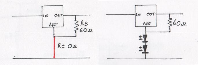 In the left hand circuit I've changed Rb to 60 ohms and Rc to zero ohms -
it's still a 1.25 volt supply but this time the only load is the 60 ohm
resistor. The current through Rb is (I= V/R) = 1.25/60 = 0.02 amps or 20
milliamps. The current through Rc - the wire now coloured in red - will also
be 20 milliamps - in fact anything we care to use as Rc will have 20 milliamps
flowing through it as long as the input voltage is high enough to drive the
load we put there. Whatever we do, the current in "Rc" will not exceed 20
milliamps.
In the left hand circuit I've changed Rb to 60 ohms and Rc to zero ohms -
it's still a 1.25 volt supply but this time the only load is the 60 ohm
resistor. The current through Rb is (I= V/R) = 1.25/60 = 0.02 amps or 20
milliamps. The current through Rc - the wire now coloured in red - will also
be 20 milliamps - in fact anything we care to use as Rc will have 20 milliamps
flowing through it as long as the input voltage is high enough to drive the
load we put there. Whatever we do, the current in "Rc" will not exceed 20
milliamps.
I chose 60 ohms (and therefore 20 milliamps) because that is the current
specified for most LEDs - we could connect an LED in place of Rc - or two
LEDs as in the right hand drawing - the current will still be fixed at 20
milliamps.
If the input is around 14 volts (which is normal for a car battery on
charge ie: with the engine running) we should allow about 4 volts "headroom"
for satisfactory operation of the LM317T then we can place a load at Rc which
could have up to 8.75 volts across it (10v - 1.25v). If the LEDs we use
have 2.0 volts across them at 20 milliamps then we could connect
up to 3 LEDs in series at "Rc" and they would all have their
specified 20 milliamps flowing through them.
The voltage at the adjust pin would be 2.0 x 3 = 6 volts. There would be
1.25 volts across Rb so the voltage at the output pin of the LM317T would be
7.25 volts.
Two diodes to protect against any damage from reverse currents can also be fitted
to the LM317T when it's used as a current regulator